ADC INTERFACING WITH ARDUINO
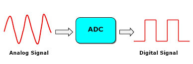
In this tutorial we are introducing concept of ADC (Analog to Digital Conversion) in ARDUINO. An analog-to-digital converter (ADC, A/D, or A-to-D) is a system that converts an analog signal.
Synopsis

In this tutorial we are introducing concept of ADC (Analog to Digital Conversion) in ARDUINO. Arduino board has six ADC channels. Among those any one or all of them can be used as inputs for analog voltage. The Arduino ADC is of 10 bit resolution (so the integer values from (0-(2^10) 1023)). This means that it will map input voltages between 0 and 5 volts into integer values between 0 and 1023.

Description

An analog-to-digital converter (ADC, A/D, or A-to-D) is a system that converts an analog signal, such as an input analog voltage or current to a digital number representing the magnitude of the voltage or current. Typically the digital output is a two's complement binary number that is proportional to the input.

The Arduino has an ADC (Analog to Digital Converter) which is connected to various input pins on the board. They are labelled as A0 to A5. The results are a number in the range 0 to 1023. Using default settings, a return value of 0 would represent approximately 0V, and a return value of 1023 (the maximum) would represent approximately 5V.

The ADC takes 13 ADC clock cycles to perform a conversion, except the first one after the ADC is enabled, at which time it takes 25 ADC cycles, while the circuitry is initialized. You can choose various prescalers, from 2 to 128. This divides down the processor clock speed to give an ADC clock speed. You can do that by changing the ADCSRA register.

The conversion time will be 13 times the clock period (or 25 for the first conversion) thus each one would be (assuming a 16 MHz clock).

Prescaler

2 * 13 * 1/16E6 = 0.000001625 ( 1.625 µs)

4 * 13 * 1/16E6 = 0.00000325 ( 3.25 µs)

8 * 13 * 1/16E6 = 0.0000065 ( 6.5 µs)

16 * 13 * 1/16E6 = 0.000013 ( 13 µs)

32 * 13 * 1/16E6 = 0.000026 ( 26 µs)

64 * 13 * 1/16E6 = 0.000052 ( 52 µs)

128 * 13 * 1/16E6 = 0.000104 (104 µs)

Taking the inverse of the period we can work out the maximum theoretical conversion rate per second.

There is an extra time before a conversion starts. The conversion starts on the leading edge of the ADC clock, not the moment the code asks for it. In the case of a scaler of 128, there could be 127 extra (processor) clock cycles added, because the hardware has to wait for the next ADC clock cycle. This could add 7.938 µs to the conversion time.

Using a lower prescaler will not only make the conversion faster, but will also reduce this wait time. A more accurate average conversion time would be 13.5 times the ADC clock time, as that 0.5 clock cycles allows for you having to wait, on average, half a clock cycle.

Using a lower prescaler will not only make the conversion faster, but will also reduce this wait time. A more accurate average conversion time would be 13.5 times the ADC clock time, as that 0.5 clock cycles allows for you having to wait, on average, half a clock cycle.

Proteus design for ADC interfacing with Arduino


Orcad design for ADC interfacing with Arduino


ADC interfacing with Arduino

/*  Name     : main.c
 *  Purpose  : Source code for ADC Interfacing with Arduino.
 *  Author   : Gemicates
 *  Date     : 22-01-2018
 *  Website  : www.gemicates.org
 *  Revision : None
 */

#include <LiquidCrystal.h>

// initialize the library with the numbers of the interface pins

LiquidCrystal lcd(4, 5, 6, 7, 8, 9, 10, 11, 12, 13);        // REGISTER SELECT PIN, ENABLE, D0, D1, D2, D3, D4, D5, D6, D7 PINS
char ADCSHOW[5];                                            // initializing a character of size 5 for showing the ADC result

void setup()
{
lcd.begin(16, 2);                                           // initializes the 16*2 LCD
}

void loop()
{
  lcd.setCursor(0, 0);                                      // set the cursor to row 0, column 0
  lcd.print("GEMICATES LABS");                              // print name
  lcd.setCursor(0, 1);                                      // set the cursor to row 0, column 1
  lcd.print("ADC RESULT:");                                 // print name
  String ADCVALUE = String (analogRead(A1));                // intailizing a string and storing ADC value in it 
  ADCVALUE.toCharArray(ADCSHOW, 5);                         // convert the reading to a char array 
  lcd.print(ADCSHOW);                                       // showing character of ADCSHOW
  lcd.print("                ");
}

Error message here!

Show Error message here!


Forgot your password?

Error message here!

Send OTP

Error message here!

Show Error message here!


Lost your password? Please enter your email address. You will receive a password you Need.

Send Error message here!


Back to log-in

Close